Continuamos con el “cursillo” de PIC en C con algo que he conseguido simular hoy. Tan simple como utilizar funciones predefinidas en una librería y tan importante como otra nueva salida al exterior de la información que maneja nuestro PIC. Se trata de escribir en una LCD un par de frases y un relojito. Algo tal que así aunque luego me ocuparé de mejorarlo:
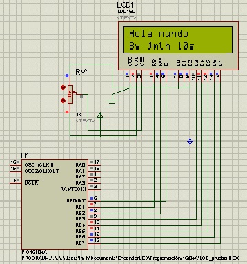
Como no se ve muy bien, he conectado RB0 al pin Enable (6), RB1 a RS(4) y RB2 a RW(5).
La configuración de la alimentación de la LCD es la siguiente: alimentamos directamente VDD y ponemos VSS a tierra. VEE es el control del contraste de nuestra pantalla (que en simulación no funciona). Tomamos de VDD a un potenciómetro (normalmente de 10K Ohm) y conectamos el pin intermedio (el variable) a VEE. El otro extremo del potenciómetro va a tierra.
En programación: hay que declarar qué puerto usar antes de añadir la librería, en éste caso he utilizado la lcd.c que viene por defecto en CCS, aunque existen por internet versiones flex_lcd.c en las que defines los pines uno a uno. Allá vamos. También hay dos formas de controlar el LCD: por 8 o 4 bits. He utilizado la configuración de 8. La LCD es de 2×16. 16 caracteres y 2 líneas.
#include <16f84a.h>
#use delay(clock=4000000)
#fuses NOWDT,NOPROTECT
#define LCD_DATA_PORT getenv("SFR:PORTB") //Se define el puerto B como datos
#include <lcd.c> //incluimos la librería por defecto
int i; //variable que utilizaremos para contar segundos
void main(){
 lcd_init(); //Éste comando inicializa la LCD automáticamente
 delay_ms(20); //*1
 i=0; //inicializamos variable a 0
 while(1){
 lcd_putc("\fHola mundo"); //limpia la pantalla y escribe Hola mundo
 lcd_gotoxy(1,2); //baja a primer caracter segunda linea
 printf(lcd_putc,"By jmth %ds",i); //imprime By jmth y la variable entera i
 delay_ms(1000); //retardo de 1s
 i++; //subimos 1 a la var
 if(i>60) i=0; //si pasa de 1 min que vuelva a 0
 }
}
//*1: En usos reales se deberá hacer un pequeño delay entre cada instrucción
// debido a lo que tarda el controlador de LCD en procesar cada una
También cabe añadir las otras 2 funciones de putc o printf, \b, que retrocede un caracter, y \n, que pasa a la siguiente línea. Si no tenéis la librería lcd.c aquí la dejo:
///////////////////////////////////////////////////////////////////////////////
//// LCD.C ////
//// Driver for common LCD modules ////
//// ////
//// lcd_init() Must be called before any other function. ////
//// ////
//// lcd_putc(c) Will display c on the next position of the LCD. ////
//// The following have special meaning: ////
//// \f Clear display ////
//// \n Go to start of second line ////
//// \b Move back one position ////
//// ////
//// lcd_gotoxy(x,y) Set write position on LCD (upper left is 1,1) ////
//// ////
//// lcd_getc(x,y) Returns character at position x,y on LCD ////
//// ////
//// CONFIGURATION ////
//// The LCD can be configured in one of two ways: a.) port access or ////
//// b.) pin access. Port access requires the entire 7 bit interface ////
//// connected to one GPIO port, and the data bits (D4:D7 of the LCD) ////
//// connected to sequential pins on the GPIO port. Pin access ////
//// has no requirements, all 7 bits of the control interface can ////
//// can be connected to any GPIO using several ports. ////
//// ////
//// To use port access, #define LCD_DATA_PORT to the SFR location of ////
//// of the GPIO port that holds the interface, -AND- edit LCD_PIN_MAP ////
//// of this file to configure the pin order. If you are using a ////
//// baseline PIC (PCB), then LCD_OUTPUT_MAP and LCD_INPUT_MAP also must ////
//// be defined. ////
//// ////
//// Example of port access: ////
//// #define LCD_DATA_PORT getenv("SFR:PORTD") ////
//// ////
//// To use pin access, the following pins must be defined: ////
//// LCD_ENABLE_PIN ////
//// LCD_RS_PIN ////
//// LCD_RW_PIN ////
//// LCD_DATA0 ////
//// LCD_DATA1 ////
//// LCD_DATA2 ////
//// LCD_DATA3 ////
//// LCD_DATA4 ////
//// ////
//// Example of pin access: ////
//// #define LCD_ENABLE_PIN PIN_E0 ////
//// #define LCD_RS_PIN PIN_E1 ////
//// #define LCD_RW_PIN PIN_E2 ////
//// #define LCD_DATA0 PIN_D4 ////
//// #define LCD_DATA1 PIN_D5 ////
//// #define LCD_DATA2 PIN_D6 ////
//// #define LCD_DATA3 PIN_D7 ////
//// ////
///////////////////////////////////////////////////////////////////////////////
//// (C) Copyright 1996,2009 Custom Computer Services ////
//// This source code may only be used by licensed users of the CCS C ////
//// compiler. This source code may only be distributed to other ////
//// licensed users of the CCS C compiler. No other use, reproduction ////
//// or distribution is permitted without written permission. ////
//// Derivative programs created using this software in object code ////
//// form are not restricted in any way. ////
///////////////////////////////////////////////////////////////////////////
typedef struct
{ // This structure is overlayed
 BOOLEAN enable; // on to an I/O port to gain
 BOOLEAN rs; // access to the LCD pins.
 BOOLEAN rw; // The bits are allocated from
 BOOLEAN unused; // low order up. ENABLE will
 int data : 4; // be LSB pin of that port.
 #if defined(__PCD__) // The port used will be LCD_DATA_PORT.
 int reserved: 8;
 #endif
} LCD_PIN_MAP;
#if defined(__PCB__)
 // these definitions only need to be modified for baseline PICs.
 // all other PICs use LCD_PIN_MAP or individual LCD_xxx pin definitions.
/* EN, RS, RW, UNUSED, DATA */
 const LCD_PIN_MAP LCD_OUTPUT_MAP = {0, 0, 0, 0, 0};
 const LCD_PIN_MAP LCD_INPUT_MAP = {0, 0, 0, 0, 0xF};
#endif
#ifndef LCD_ENABLE_PIN
 #define lcd_output_enable(x) lcdlat.enable=x
 #define lcd_enable_tris() lcdtris.enable=0
#else
 #define lcd_output_enable(x) output_bit(LCD_ENABLE_PIN, x)
 #define lcd_enable_tris() output_drive(LCD_ENABLE_PIN)
#endif
#ifndef LCD_RS_PIN
 #define lcd_output_rs(x) lcdlat.rs=x
 #define lcd_rs_tris() lcdtris.rs=0
#else
 #define lcd_output_rs(x) output_bit(LCD_RS_PIN, x)
 #define lcd_rs_tris() output_drive(LCD_RS_PIN)
#endif
#ifndef LCD_RW_PIN
 #define lcd_output_rw(x) lcdlat.rw=x
 #define lcd_rw_tris() lcdtris.rw=0
#else
 #define lcd_output_rw(x) output_bit(LCD_RW_PIN, x)
 #define lcd_rw_tris() output_drive(LCD_RW_PIN)
#endif
#ifndef LCD_DATA_PORT
 #if defined(__PCB__)
 #define LCD_DATA_PORT 0x06 //portb
 #define set_tris_lcd(x) set_tris_b(x)
 #elif defined(__PCM__)
 #define LCD_DATA_PORT getenv("SFR:PORTD") //portd
 #elif defined(__PCH__)
 #define LCD_DATA_PORT getenv("SFR:PORTD") //portd
 #elif defined(__PCD__)
 #define LCD_DATA_PORT getenv("SFR:PORTD") //portd
 #endif
#endif
#if defined(__PCB__)
 LCD_PIN_MAP lcd, lcdlat;
 #byte lcd = LCD_DATA_PORT
 #byte lcdlat = LCD_DATA_PORT
#elif defined(__PCM__)
 LCD_PIN_MAP lcd, lcdlat, lcdtris;
 #byte lcd = LCD_DATA_PORT
 #byte lcdlat = LCD_DATA_PORT
 #byte lcdtris = LCD_DATA_PORT+0x80
#elif defined(__PCH__)
 LCD_PIN_MAP lcd, lcdlat, lcdtris;
 #byte lcd = LCD_DATA_PORT
 #byte lcdlat = LCD_DATA_PORT+9
 #byte lcdtris = LCD_DATA_PORT+0x12
#elif defined(__PCD__)
 LCD_PIN_MAP lcd, lcdlat, lcdtris;
 #word lcd = LCD_DATA_PORT
 #word lcdlat = LCD_DATA_PORT+2
 #word lcdtris = LCD_DATA_PORT-0x02
#endif
#ifndef LCD_TYPE
 #define LCD_TYPE 2 // 0=5x7, 1=5x10, 2=2 lines
#endif
#ifndef LCD_LINE_TWO
 #define LCD_LINE_TWO 0x40 // LCD RAM address for the second line
#endif
BYTE const LCD_INIT_STRING[4] = {0x20 | (lcd_type << 2), 0xc, 1, 6};
 // These bytes need to be sent to the LCD
 // to start it up.

BYTE lcd_read_nibble(void);
BYTE lcd_read_byte(void)
{
 BYTE low,high;
#if defined(__PCB__)
 set_tris_lcd(LCD_INPUT_MAP);
 #else
 #if (defined(LCD_DATA0) && defined(LCD_DATA1) && defined(LCD_DATA2) && defined(LCD_DATA3))
 output_float(LCD_DATA0);
 output_float(LCD_DATA1);
 output_float(LCD_DATA2);
 output_float(LCD_DATA3);
 #else
 lcdtris.data = 0xF;
 #endif
 #endif

 lcd_output_rw(1);
 delay_cycles(1);
 lcd_output_enable(1);
 delay_cycles(1);
 high = lcd_read_nibble();

 lcd_output_enable(0);
 delay_cycles(1);
 lcd_output_enable(1);
 delay_us(1);
 low = lcd_read_nibble();

 lcd_output_enable(0);
#if defined(__PCB__)
 set_tris_lcd(LCD_INPUT_MAP);
 #else
 #if (defined(LCD_DATA0) && defined(LCD_DATA1) && defined(LCD_DATA2) && defined(LCD_DATA3))
 output_drive(LCD_DATA0);
 output_drive(LCD_DATA1);
 output_drive(LCD_DATA2);
 output_drive(LCD_DATA3);
 #else
 lcdtris.data = 0x0;
 #endif
 #endif
return( (high<<4) | low);
}
BYTE lcd_read_nibble(void)
{
 #if (defined(LCD_DATA0) && defined(LCD_DATA1) && defined(LCD_DATA2) && defined(LCD_DATA3))
 BYTE n = 0x00;
/* Read the data port */
 n |= input(LCD_DATA0);
 n |= input(LCD_DATA1) << 1;
 n |= input(LCD_DATA2) << 2;
 n |= input(LCD_DATA3) << 3;

 return(n);
 #else
 return(lcd.data);
 #endif
}
void lcd_send_nibble(BYTE n)
{
 #if (defined(LCD_DATA0) && defined(LCD_DATA1) && defined(LCD_DATA2) && defined(LCD_DATA3))
 /* Write to the data port */
 output_bit(LCD_DATA0, BIT_TEST(n, 0));
 output_bit(LCD_DATA1, BIT_TEST(n, 1));
 output_bit(LCD_DATA2, BIT_TEST(n, 2));
 output_bit(LCD_DATA3, BIT_TEST(n, 3));
 #else
 lcdlat.data = n;
 #endif

 delay_cycles(1);
 lcd_output_enable(1);
 delay_us(2);
 lcd_output_enable(0);
}
void lcd_send_byte(BYTE address, BYTE n)
{
 lcd_output_rs(0);
 while ( bit_test(lcd_read_byte(),7) ) ;
 lcd_output_rs(address);
 delay_cycles(1);
 lcd_output_rw(0);
 delay_cycles(1);
 lcd_output_enable(0);
 lcd_send_nibble(n >> 4);
 lcd_send_nibble(n & 0xf);
}
void lcd_init(void)
{
 BYTE i;
#if defined(__PCB__)
 set_tris_lcd(LCD_OUTPUT_MAP);
 #else
 #if (defined(LCD_DATA0) && defined(LCD_DATA1) && defined(LCD_DATA2) && defined(LCD_DATA3))
 output_drive(LCD_DATA0);
 output_drive(LCD_DATA1);
 output_drive(LCD_DATA2);
 output_drive(LCD_DATA3);
 #else
 lcdtris.data = 0x0;
 #endif
 lcd_enable_tris();
 lcd_rs_tris();
 lcd_rw_tris();
 #endif
lcd_output_rs(0);
 lcd_output_rw(0);
 lcd_output_enable(0);

 delay_ms(15);
 for(i=1;i<=3;++i)
 {
 lcd_send_nibble(3);
 delay_ms(5);
 }

 lcd_send_nibble(2);
 for(i=0;i<=3;++i)
 lcd_send_byte(0,LCD_INIT_STRING[i]);
}
void lcd_gotoxy(BYTE x, BYTE y)
{
 BYTE address;
if(y!=1)
 address=LCD_LINE_TWO;
 else
 address=0;

 address+=x-1;
 lcd_send_byte(0,0x80|address);
}
void lcd_putc(char c)
{
 switch (c)
 {
 case '\f' : lcd_send_byte(0,1);
 delay_ms(2);
 break;

 case '\n' : lcd_gotoxy(1,2); break;

 case '\b' : lcd_send_byte(0,0x10); break;

 default : lcd_send_byte(1,c); break;
 }
}

char lcd_getc(BYTE x, BYTE y)
{
 char value;
lcd_gotoxy(x,y);
 while ( bit_test(lcd_read_byte(),7) ); // wait until busy flag is low
 lcd_output_rs(1);
 value = lcd_read_byte();
 lcd_output_rs(0);

 return(value);
}


